
Benefits of HVAC BIM Coordination Across Building Disciplines
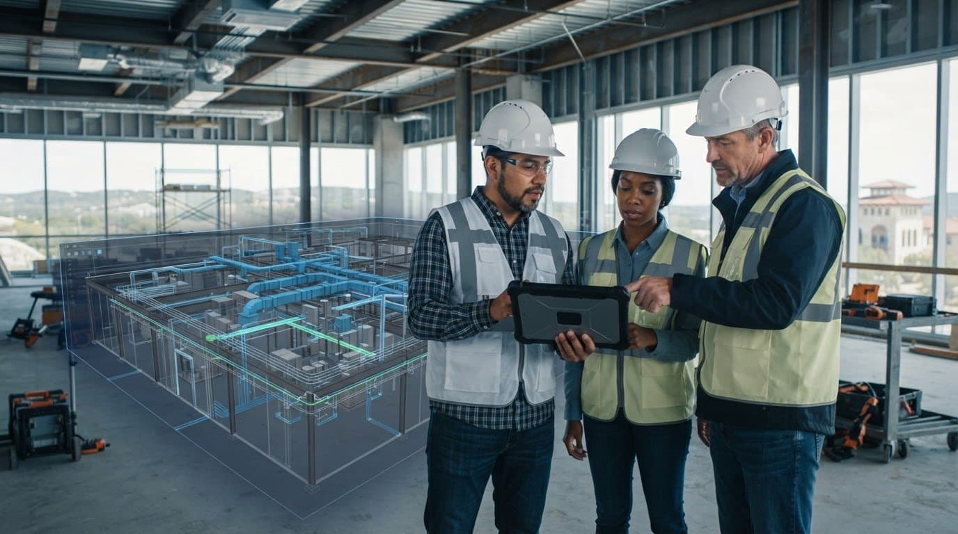
A duct route that looks clear on a drawing can still conflict with structural steel, electrical pathways, or another trade’s equipment. The benefits of HVAC BIM coordination are practical: teams can spot spatial conflicts before installation, refine layouts, reduce avoidable errors, and prepare coordinated information for fabrication. Mechanical BIM modeling brings HVAC equipment and routing into a shared digital view, making it easier to assess how systems fit within a building.
HVAC plans need to work alongside structural, electrical, plumbing, and architectural designs, not in isolation. Yet crowded ceiling spaces, risers, and plant rooms leave little room for late changes. Maintenance access and installation sequencing matter, too. BIM coordination helps teams examine these constraints earlier, when design adjustments can be planned rather than improvised in the field.
This article explains mechanical BIM modeling in MEP projects, how clash detection exposes conflicts, and how coordinated models support documentation and fabrication planning. It also shows how sharing HVAC information across building disciplines helps teams align system routes, equipment locations, and installation requirements before construction advances.
Key Takeaways
- Use automated clash detection to flag spatial conflicts and access constraints while HVAC layouts can still be coordinated with other trades.
- Understand how mechanical BIM models combine HVAC equipment, system routes, and technical information in a shared digital building model.
- Review conflicts early to help limit construction-stage revisions, installation delays, and avoidable rework.
- Use coordinated model information to improve documentation accuracy and support fabrication planning.
- Align HVAC routing, equipment placement, and installation needs with architectural, structural, electrical, and plumbing systems.
What are the advantages of using dedicated clash detection solutions for HVAC modeling?
Dedicated clash detection compares HVAC layouts with other building systems in a coordinated model. It helps teams identify spatial conflicts and resolve them before construction drawings and installation plans advance.
Automated Clash Checks
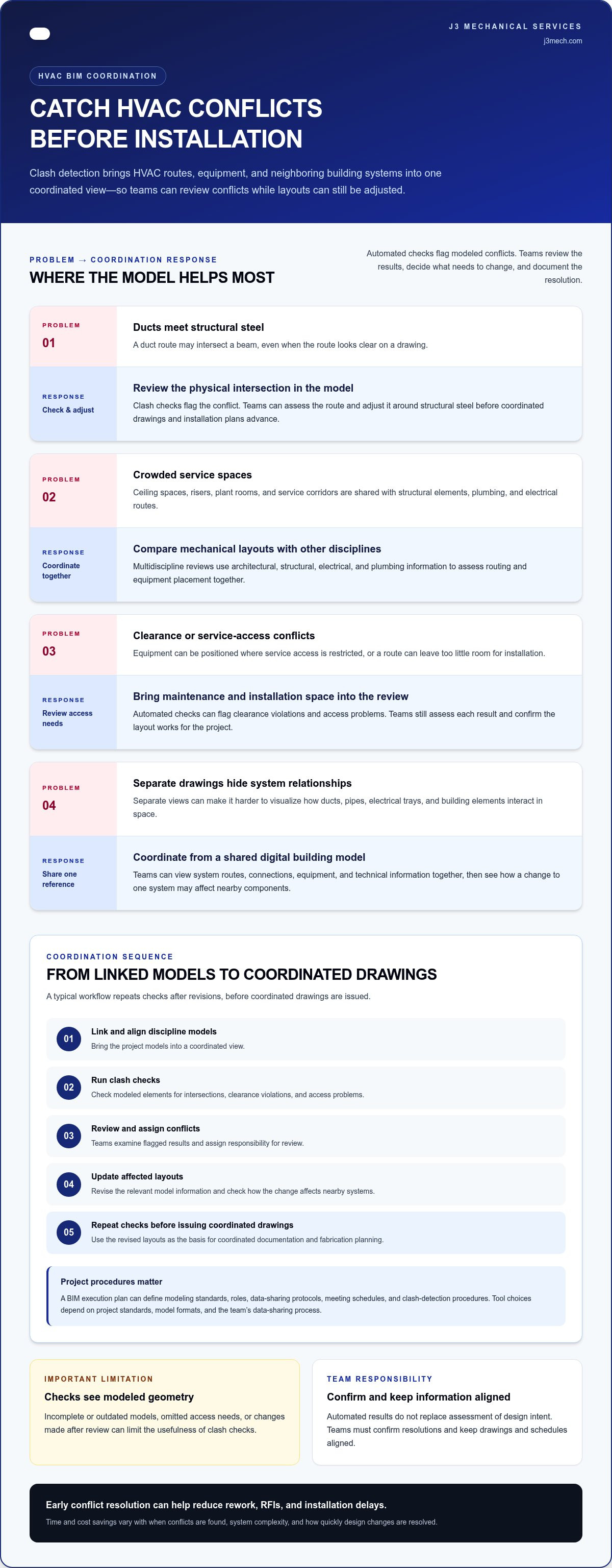
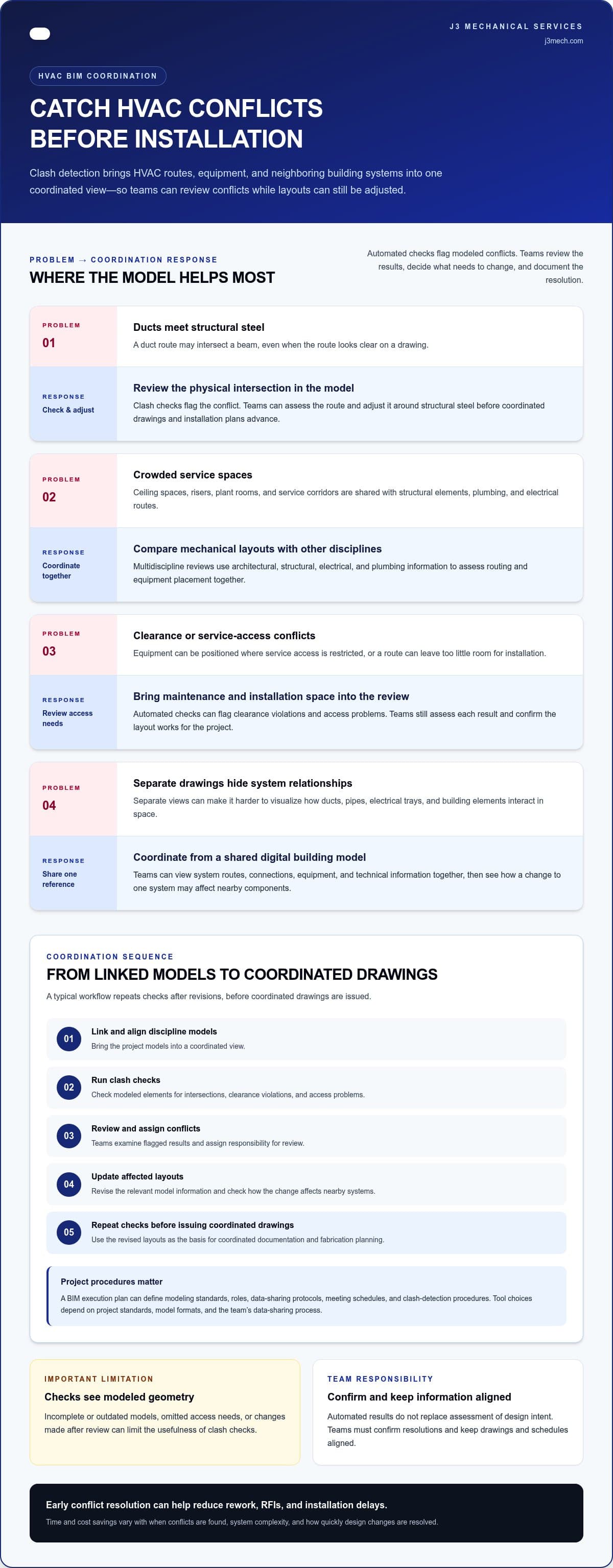
Automated clash detection checks model elements for physical intersections, clearance violations, and access problems. For example, a clash review can flag a duct crossing a beam or equipment positioned where service access is restricted. Teams can then review each result, determine whether it requires a design change, and document the resolution. This focused review supports collaboration by turning model conflicts into defined coordination tasks.
Structural and Building Services Conflicts
HVAC systems share ceiling spaces, risers, plant rooms, and service corridors with structural elements, plumbing, and electrical routes. A duct may intersect a beam, or a pipe or electrical tray may obstruct its planned route. Reviewing these relationships in the model helps teams assess routing and equipment placement together. It also brings maintenance access and installation space into the discussion before site conditions limit the options.
Multidiscipline Coordination
Multidiscipline clash detection compares the mechanical model with architectural, structural, electrical, and plumbing information. In a coordinated review, teams examine flagged conflicts, assign responsibility, update the affected model, and check the revised layout. This process gives disciplines a shared reference rather than relying on separate drawings and assumptions. BIM execution plans typically define modeling standards, roles, data-sharing protocols, meeting schedules, and clash-detection procedures. ISO 19650 is an international BIM information management standard, according to the International Organization for Standardization.
Ductwork Trade Clash Avoidance
Ductwork coordination examines routing, dimensions, connected equipment, nearby services, and required access. A duct route can be adjusted around structural steel or electrical containment before fabrication information is prepared. Updated drawings and model data then give trades a clearer reference for installation planning and material coordination. This comparison is more spatially informative than traditional 2D coordination, where separate views can make interactions between components harder to visualize.
In the United States, project requirements are generally communicated through project BIM standards and the BIM execution plan. That plan can define the coordination process; ISO 19650 provides an international information-management standard, not a project-specific layout.
Time and cost savings depend on when teams find conflicts, system complexity, and how quickly design changes are resolved. Early resolution can reduce rework, RFIs, and installation delays, but savings vary by project.
HVAC BIM coordination uses BIM authoring software to create system models and model-checking tools to compare them. Tool choices depend on project standards, model formats, and the team’s data-sharing process.
A typical workflow links and aligns discipline models, runs clash checks, reviews and assigns conflicts, updates affected layouts, then repeats checks before issuing coordinated drawings. The BIM execution plan sets project procedures and responsibilities.
Limitations arise when models contain incomplete or outdated information, omit access needs, or change after review. Automated checks identify conflicts in modeled geometry, but teams must still assess design intent, confirm resolutions, and keep drawings and schedules aligned.
What Is Mechanical BIM Modeling in MEP Projects?
Mechanical BIM modeling represents HVAC equipment and distribution systems in a digital building model, including geometry and technical information. This gives project teams a coordinated view of system layouts, connections, and spatial requirements.
Ductwork and Mechanical Piping
Ductwork and mechanical piping models show system routes, component locations, and equipment connections within the building. A model may include ducts, pipes, air terminals, pumps, chillers, and air-handling units. Reviewing these elements alongside structural and architectural models helps contractors understand available space and how systems connect. Technical parameters add useful context beyond lines on a plan.
Shared Models for Team Collaboration
A shared project model gives architects, engineers, contractors, and project managers a common reference for building information. Team members can view updates and assess how a change to one system affects nearby components. For example, shifting a duct route may prompt a review of nearby piping or electrical layouts. Shared access supports collaboration and reduces reliance on separate, cross-referenced drawings.
Three-Dimensional System Modeling
Three-dimensional models represent HVAC systems spatially, so teams can inspect routes, equipment placement, and clearances from different views. A plan view may show a duct’s direction, while a three-dimensional view clarifies its relationship to a beam or nearby equipment. The model can also carry performance specifications, installation requirements, and operational parameters, allowing project teams to consider system data alongside physical fit.
Mechanical models can include air-handling units, chillers, cooling towers, boilers, circulation pumps, ductwork, mechanical piping, diffusers, and air distribution terminals. Each component adds information about its position and connection to the wider system. This makes the model useful for assessing how HVAC elements occupy ceiling spaces, plant rooms, and service areas, rather than viewing each component in isolation.
A model can remain useful after construction when equipment locations and system specifications are retained for facility management. As-built information helps facility teams locate valves, equipment, and access points during maintenance or future renovations, streamlining the ongoing HVAC repair Maryland commercial facilities depend on to maintain efficient climate control. A coordinated model can also give owners a clearer basis for planning upgrades than outdated paper drawings or incomplete records.
For commercial projects, Building Information Modeling can connect mechanical system information with the wider building model, supporting coordination from design through construction.
Early detection of trade and system conflicts
Early conflict detection means reviewing coordinated building models while design decisions can still change. Engineers can compare HVAC routes with structural, electrical, and plumbing layouts before installation planning advances. For example, a duct route that meets a beam can be revised digitally rather than discovered when crews reach that ceiling area. This gives the project team a clearer basis for evaluating options.
Traditional drawings separate systems into discipline-specific views, making some spatial relationships hard to assess together. In a coordinated model, an engineer can inspect a ceiling zone containing ductwork, piping, electrical containment, and structural framing. This helps reveal whether systems compete for space or leave too little room for installation and access. The detail is especially useful in congested risers, plant rooms, and service corridors.
Conflicts are not limited to physical intersections. A duct may clear a beam but block access to nearby equipment, while a pipe route may constrain an electrical pathway. Model reviews can flag physical interferences, clearance violations, and access issues separately. This helps teams decide whether to adjust a route, reposition equipment, or preserve space for maintenance and installation.
A structured review turns each detected issue into a coordination task. Teams identify the affected elements, assess the conflict, assign the design update, and review the revised model. For example, routing a duct around a structural member may require engineers to check connected branches and equipment connections. Rechecking the layout helps ensure that resolving one conflict does not create another nearby.
Early review also helps teams prioritize decisions by their effect on other workflows. A large duct passing through a tight ceiling zone may affect electrical and plumbing routes, while a local adjustment may affect only one branch. Reviewing those relationships together helps teams coordinate a solution instead of shifting the problem to another trade. The aim is a more workable installation sequence.
Resolved conflicts can inform updated drawings and coordination records before construction documents are issued. When a model change affects several systems, teams can review the shared detail and align their information. This lowers the risk of trades using inconsistent layouts or discovering that a planned route no longer fits. Clear coordination supports better decisions about routing, access, and installation.
For example, if a mechanical route blocks an electrician’s access path, the team can compare alternatives before site work begins. The review considers the duct’s connections, nearby piping, structural constraints, and electrical work area. Finding the issue early gives each discipline time to coordinate the change and update its workflow, rather than resolving the conflict during active construction.
Error reduction and precise fabrication
Mechanical BIM can connect coordinated design information with fabrication and installation planning. A model containing duct dimensions, fittings, equipment connections, and system routes gives teams a detailed basis for preparing components. This can reduce manual takeoffs, where repeated measurements or calculations may introduce errors. Model-derived material quantities, for example, can support procurement planning and give the fabrication team a consistent reference.
Fabrication-ready detail depends on the model’s purpose and development. LOD 400 HVAC models provide fabrication-level ductwork and piping, including accurate dimensions, fittings, and connections. Those details can support shop drawings and prefabrication when the model is coordinated for that use. A duct assembly can be planned from its modeled route and connection points, rather than interpreted only from separate design views.
Before components are manufactured, model quality reviews can check geometry accuracy, data consistency, system connectivity, equipment clearances, version tracking, and documentation. Each check addresses a different potential source of error. Reviewing a duct connection alongside connected equipment, for instance, can expose a mismatch before fabrication. Version tracking helps teams use current information when design updates affect assembly drawings.
Coordinated model outputs can include mechanical spool drawings, equipment connection layouts, prefabricated-component assembly drawings, hanger and support layouts, and insulation allowances. These documents translate model information into practical fabrication and installation references. A hanger layout, for example, can show support positions relative to the modeled duct route, while an equipment connection drawing clarifies how a component joins the system.
Prefabrication moves selected assembly work away from the construction site. Accurate digital layouts can guide the manufacture of pipes, ducts, and other mechanical components before delivery. This supports quality control during assembly and can reduce on-site labor needs. Transport and installation planning remain important, since fabricated sections must fit access routes and the final equipment location.
Model-based schedules, equipment lists, and material quantities give procurement teams clearer information for coordinating orders with installation needs. If a design revision changes a duct branch or pipe connection, teams can review the affected quantities and drawings together. This helps limit discrepancies between the intended layout, purchased materials, and fabricated components, while giving field teams a consistent installation reference.
Mechanical BIM models can support in-house fabrication by linking coordinated design information with production planning. The useful outcome is not simply a three-dimensional component, but a reviewed set of dimensions, connections, supports, and documentation that can guide manufacturing. When design changes occur, updating the model and associated fabrication information helps teams manage revisions before they become site rework or installation adjustments.
HVAC system coordination across building disciplines
HVAC BIM coordination brings mechanical layouts together with architectural, structural, electrical, and plumbing information in a shared digital model. Building information modeling lets teams review how HVAC systems fit the facility as a whole, not just within mechanical drawings. Its central value is a coordinated reference for decisions about routes, equipment locations, access, and installation sequence.
Consider a ceiling zone where a supply duct, structural beam, lighting route, and plumbing line converge. Coordinated views help teams assess the available space before construction. If the duct route needs adjustment, the team can consider its connections and surrounding services in context. That shared detail can help avoid shifting a design problem from one trade to another.
Coordination also connects system layouts with building use and access needs. For example, a variable air volume box needs a location that allows testing, balancing, cleaning, and future replacement. Reviewing its position alongside ceiling conditions and nearby services helps preserve practical access. In a hospital, BIM can support coordination of airflow and temperature control across spaces with different mechanical requirements.
Design changes can affect several disciplines at once. If a ceiling height changes to accommodate building systems, architects and engineers can review the effects on duct routing, equipment placement, and service access. In complex commercial interiors, fit-out specialists such as Right Solution Contracting LLC rely on early spatial coordination to ensure aesthetic ceiling layouts align seamlessly with mechanical systems. Shared model updates give teams a common view of the change and help align drawings and decisions. This reduces duplicate entry and cross-referencing when multiple documents rely on the same building information.
Coordinated models can also inform construction sequencing. Teams can see whether ductwork installation would block electricians or plumbers, then adjust workflows before crews reach the area. They can review equipment placement and delivery routes against the building structure, while fabrication information follows the coordinated layout. These linked decisions connect design intent with practical installation constraints.
The model’s usefulness can continue after construction when equipment locations, specifications, and maintenance requirements remain available to facility teams. A maintained record can help locate valves or plan a future mechanical upgrade using engineering information. For projects where coordinated HVAC layouts and fabrication are central, discuss HVAC BIM coordination as part of the project planning process.
J3 Mechanical Services: Commercial HVAC Installation & Replacement
J3 Mechanical Services provides commercial HVAC installation and replacement for projects where equipment, system routes, and building conditions must align. Coordinated planning can help owners and project teams consider HVAC requirements alongside construction needs, whether installing systems in a new commercial building or replacing existing equipment.
For operating facilities, commercial HVAC maintenance and repair address ongoing mechanical system needs, while 24/7 Emergency Service supports urgent repair situations. The right service depends on whether the project involves a planned installation, replacement, scheduled upkeep, or an unexpected system issue.
To discuss commercial HVAC installation or replacement for your building, contact J3 Mechanical Services.
Carry coordinated decisions into the next project phase
The benefits of HVAC BIM coordination are most useful when model decisions stay connected to project execution. A coordinated layout can inform discussions about design changes, installation requirements, and facility priorities, keeping the next phase grounded in shared building information. Treat coordination as an ongoing project practice, not a one-time model review, so new decisions remain aligned with the building’s mechanical needs.
For owners planning a commercial HVAC project, start by clarifying the building’s requirements, existing conditions, and intended scope. These priorities help shape system design and implementation decisions, while keeping coordination focused on practical outcomes.
J3 Mechanical Services can discuss how its commercial HVAC work aligns with your project’s needs. Contact J3 Mechanical Services to start a conversation and move forward with a clear plan.
Frequently Asked Questions
How can you ensure accuracy and reduce errors in HVAC design?
Improve HVAC design accuracy by checking the model against coordinated project information and validating revisions before issue. Confirm that equipment schedules, system connections, and layout drawings reflect the same design version. A changed air-handling unit, for example, can affect duct connections and service clearances. Review geometry or data discrepancies with the responsible engineers, then update affected documents together. This disciplined process reduces inconsistencies without replacing engineering judgment.
How does BIM enhance the HVAC design process?
BIM enhances HVAC design by letting engineers assess system decisions within the building context. They can evaluate airflow, equipment placement, and energy use, then consider how a change affects adjacent systems. For example, changing a duct route may require revisiting duct sizing or terminal locations. Iterative analysis helps teams compare options before finalizing construction documents, while retained model information supports decisions as project requirements evolve.
What are some notable projects that have leveraged BIM for HVAC optimization?
BIM supports HVAC coordination across project types with demanding mechanical requirements. Hospitals can use models to coordinate airflow and temperature control, while life-sciences and pharmaceutical laboratories use BIM for accurate piping and pressurization. Data centers apply it to plan reliable cooling for sensitive equipment. These examples show how project teams can use building models to address facility-specific system needs without assuming that one HVAC layout suits every building.
What are the main benefits of HVAC BIM coordination?
The main benefits of HVAC BIM coordination include clearer design decisions, more reliable project information, and better alignment between mechanical plans and construction needs. Teams can use model data to assess equipment placement, plan material quantities, and organize fabrication information. Owners may also retain useful system details for future facility work. The value comes from connecting design decisions with the people and project phases that depend on them.
How does HVAC BIM coordination reduce clashes and rework?
HVAC BIM coordination reduces clashes by comparing modeled system locations before crews install components. When a duct conflicts with a beam or another trade’s route, teams can review the issue, assign a design update, and check the revised information. Recording decisions helps disciplines work from aligned layouts. This can prevent conflicts from becoming field rework, though the model is useful only when project information is current and sufficiently detailed.
How does HVAC BIM improve HVAC system design and energy efficiency?
BIM can support HVAC design analysis by helping engineers assess airflow, energy use, and indoor environmental conditions. They can compare options and adjust routing, sizing, or system selection in response to analysis. For instance, modeled performance information can help assess how a proposed layout affects energy use. These evaluations inform design decisions, but do not establish a building’s eventual operating performance.
How much time and cost can HVAC BIM coordination save?
Savings depend on when conflicts are found, system complexity, and how quickly teams resolve design changes. Early resolution can reduce rework, RFIs, and installation delays, but savings vary by project.
Need a hand with your building's HVAC?
Free quotes and honest answers from licensed commercial technicians across South Texas.