
Mechanical BIM Coordination in San Antonio
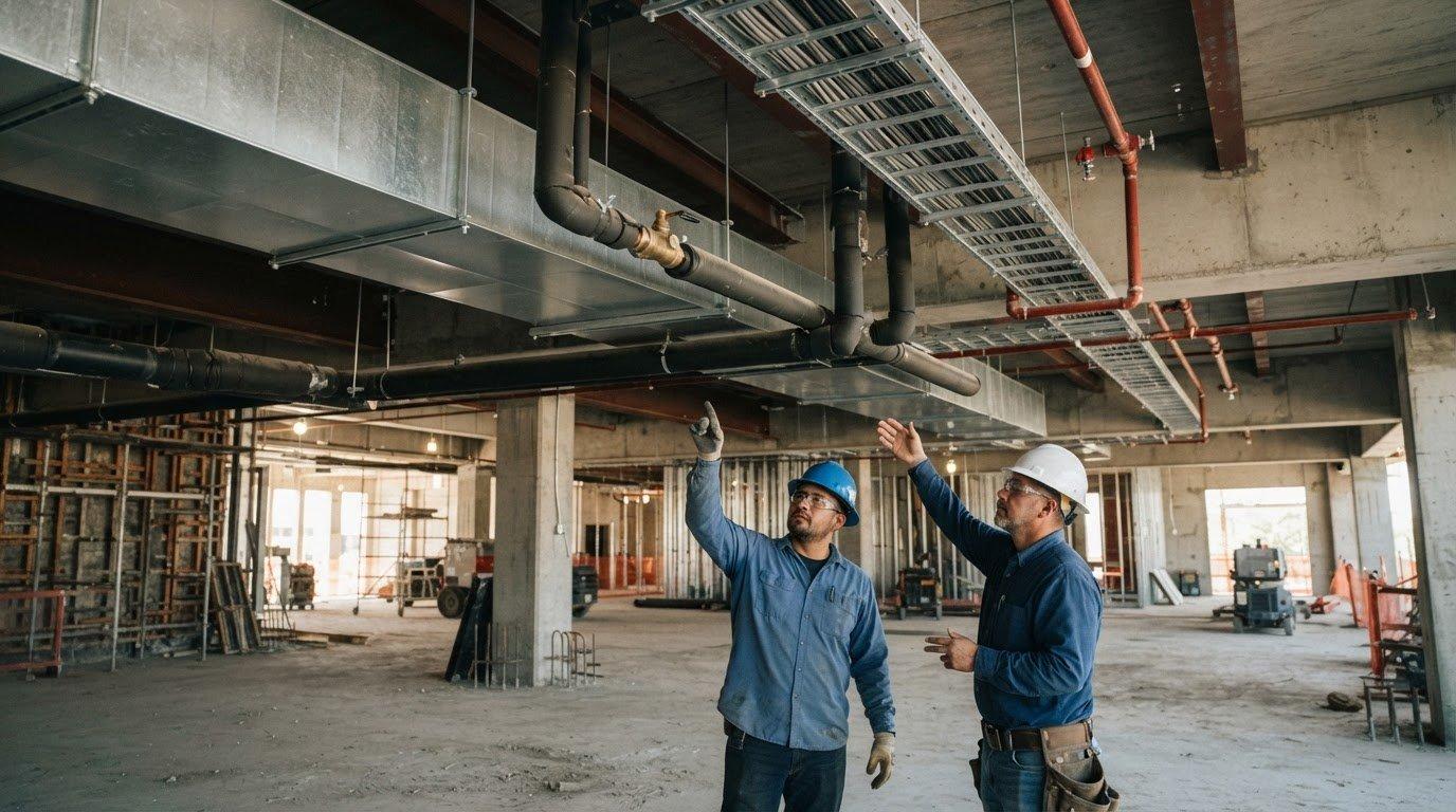
A coordinated mechanical model is more than a three-dimensional drawing; it is a way to resolve system interfaces before they become field conflicts. BIM for mechanical contractors in San Antonio brings HVAC equipment, ductwork, piping, and other building systems into a shared digital environment, where routing and spatial relationships can be reviewed before fabrication and installation.
Mechanical contractors know that coordination affects how smoothly a project moves from design into construction. BIM makes that work visible and actionable: a well-developed model can support trade coordination, fabrication planning, and clear shop drawings, while helping teams identify issues to resolve before work reaches the field.
This article explains how mechanical BIM applies to commercial projects in San Antonio and across Texas, what coordination with architectural, structural, and electrical trades involves, and how fabrication models and shop drawings support installation. It also outlines the decisions behind a useful BIM workflow, so you can see where the process fits and what to expect at each stage.
Key Takeaways
- Define the mechanical systems and level of model detail needed so the BIM scope supports the project’s design and construction needs.
- Connect coordinated models to shop drawings, fabrication planning, and bills of materials for a more organized path from digital design to field installation.
- Review mechanical routes alongside architectural, structural, and electrical systems to identify interface issues while they can still be addressed in the model.
- Evaluate BIM contractors by how their modeling and coordination process supports project handoffs, fabrication requirements, and installation sequencing.
- Use BIM where early coordination and clear mechanical documentation can strengthen project planning and execution.
Mechanical BIM modeling for HVAC, plumbing, piping, drainage, and fire protection
Mechanical BIM modeling represents building systems in a coordinated digital model, allowing their routes and equipment locations to be reviewed together. On San Antonio construction projects, standards and deliverables depend on the project; San Antonio Airport System BIM Standards reference ISO 55000:2014 for asset-management overview, principles, and terminology, and ISO 19650-2:2018 for information management during the delivery phase of assets.
Mechanical Piping and Equipment Models
A mechanical model can represent HVAC ductwork and equipment alongside plumbing, piping, drainage, and fire protection systems. In Revit, mechanical components can be modeled with custom families that represent equipment or fittings and carry useful project information.
Model development starts with placing equipment and defining system routes, then refining connections and spatial relationships. For example, a piping model can show how a pipe approaches equipment and where it runs through a ceiling zone. Reviewing these relationships supports coordination with other building systems before construction.
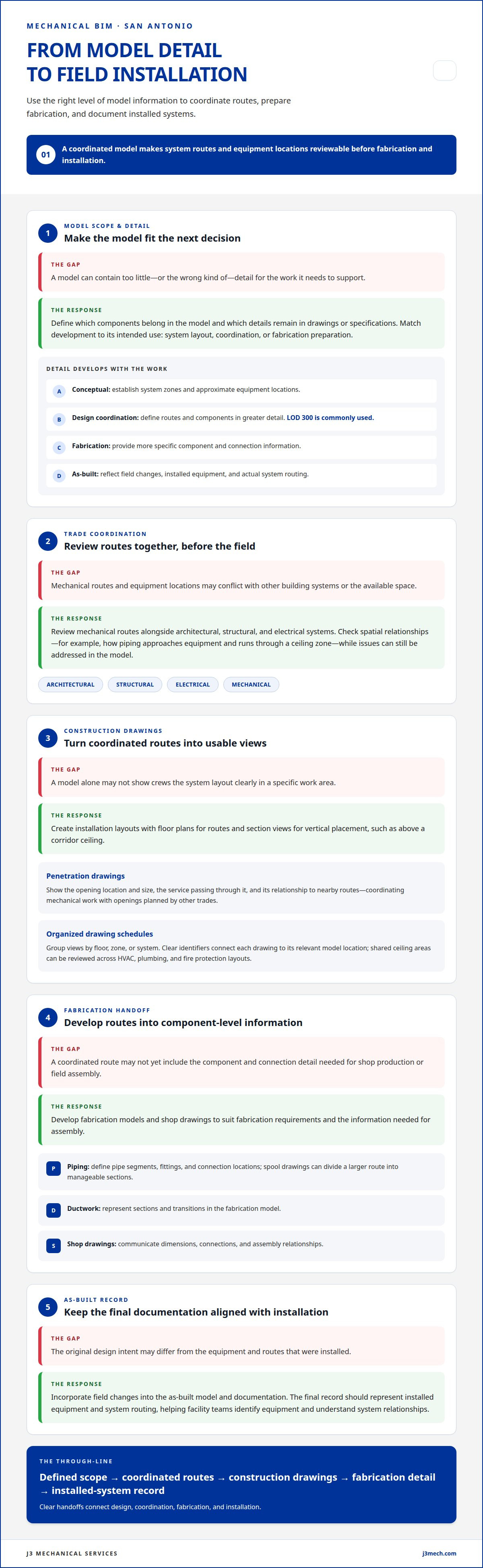
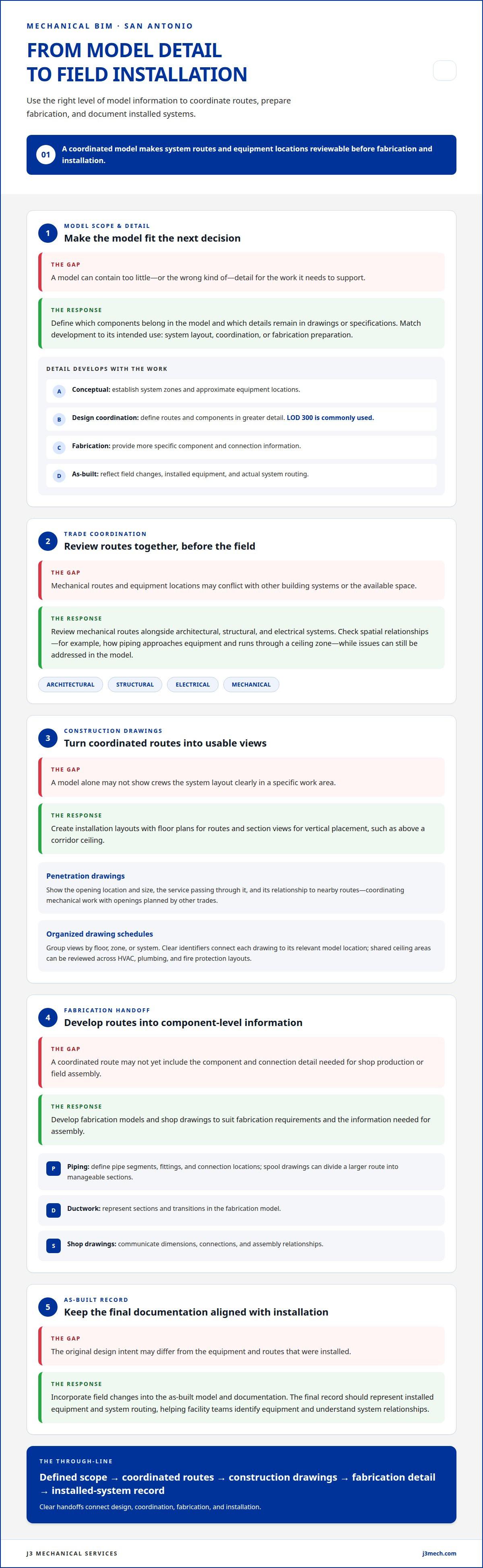
Model scope matters. Teams should distinguish components included in the model from details that remain in drawings or specifications. This keeps the model aligned with its intended use, whether the priority is system layout, coordination, or fabrication preparation.
LOD Progression and As-Built Documentation
LOD describes how much information and geometric detail a model element contains at a particular stage. A conceptual model can establish system zones and approximate equipment locations; later development can define routes and components in greater detail. LOD 300 is commonly used for design coordination.
As construction advances, teams can incorporate field changes into an as-built model and its documentation. The final record should reflect installed equipment and system routing, not just the original design intent. Organized model information can help facility teams identify equipment and understand how systems relate.
The key review is whether the model’s level of detail suits the next project decision. Coordination requires clear spatial relationships; fabrication needs more specific component and connection information; an as-built record should represent the completed installation.
BIM Benefits and Project Deliverables
Mechanical BIM deliverables may include a Revit model, coordinated views, model-based shop drawings, and as-built documentation. The package should clearly show system routes, equipment locations, and coordination decisions for the people using it during construction.
For HVAC, plumbing, and piping contractors, modeling supports trade coordination by exposing spatial conflicts and clarifying how systems fit within the building. The San Antonio Airport System BIM Standards also reference ISO 19650-1:2018 for BIM information-management concepts and principles, alongside the delivery-phase guidance in ISO 19650-2:2018.
Useful BIM coordination depends on defined model scope, consistent component information, and clear handoffs between design, coordination, fabrication, and installation. These deliverables give project teams a structured basis for reviewing mechanical work and carrying approved information into the next phase.
The SAAS basement level is listed at 771’ - 2”, the SAAS arrivals level at 785’ - 8”, and the SAAS departures level at 805’ - 0”. These elevations can serve as references when reviewing vertical system relationships.
Shop drawings, fabrication models, and bills of materials
Mechanical contractors connect coordinated BIM information to field installation through a defined sequence. They develop installation drawings, fabrication models, and material schedules from the project model, then use those deliverables to guide shop work and installation.
Installation Layouts and Penetration Drawings
Installation layouts translate modeled system routes into views crews can use in specific work areas. A floor plan might show duct and pipe routes, while a section view clarifies vertical placement above a corridor ceiling. Together, these drawings show how mechanical work fits the available space.
Sleeve and penetration drawings identify where services pass through walls, floors, or other building elements. A coordinated drawing can show an opening’s location and size, the system passing through it, and its relationship to nearby routes. This helps align mechanical installation with openings planned by other trades.
Drawing schedules can organize views by floor, zone, or system, making it easier to locate the right information during construction. For example, a fire protection layout can be issued alongside HVAC and plumbing plans for review of shared ceiling areas. Clear identifiers connect each drawing to its relevant model location.
Fabrication Models and Spool Drawings
A fabrication model develops coordinated routes into component-level information for shop production. For piping, it can define pipe segments, fittings, and connection locations; for ductwork, it can represent sections and transitions. The appropriate detail depends on fabrication requirements and the information needed for field assembly.
Fabrication-ready shop drawings communicate dimensions, connections, and assembly relationships. Spool drawings divide a larger piping route into manageable assemblies and show how each spool relates to the next. Identifying the installation area and assembly sequence connects shop production with field placement.
A bill of materials can be generated or organized from modeled components, listing items required for a defined assembly or work area. Before release, review the model and drawings together for consistent component identifiers, dimensions, and revisions. This helps prevent the drawing set from describing a different configuration than the fabrication model.
Integration works best when the model, shop drawings, and field sequence remain aligned through revisions. Changes to a route can affect spool dimensions, connection points, and material schedules, so the affected deliverables need coordinated updates before production or installation proceeds. For projects that connect modeling with in-house fabrication, this handoff keeps digital coordination tied to physical assembly.
MEP coordination across architectural, structural, and electrical trades
MEP coordination aligns mechanical routes with architectural layouts, structural elements, and electrical systems. BIM for mechanical contractors in San Antonio turns separate trade models into coordinated information teams can review before installation.
Trade Coordination Drawings
Coordination drawings combine architectural, structural, electrical, and mechanical information in shared views. Teams can check whether a duct route conflicts with a beam, light fixture, cable tray, or ceiling boundary. The U.S. Bureau of Labor Statistics describes BIM as enabling workers in several occupations to collaborate in planning a building’s physical systems.
A coordination workflow typically begins by assembling current trade models, then reviewing intersections and recording issues for resolution. Each issue should identify the affected location, systems, and responsible trade. Once teams agree on a route or adjustment, updated coordination drawings communicate the decision, while mechanical shop drawings carry relevant installation details forward.
HVAC Duct Modeling and Coordination
HVAC duct modeling shows duct routes, fittings, and equipment in relation to surrounding building elements. For example, teams can review a main duct crossing a corridor against structural beams, electrical trays, and ceiling requirements before finalizing its route.
Coordination reviews should examine more than visible intersections. Teams also consider whether duct transitions, access areas, and connections fit in the modeled space. Accurate model information makes these relationships easier to discuss and helps keep coordination drawings aligned with the mechanical design.
MEP coordination providers serving San Antonio support project workflows by combining trade information, identifying conflicts, and documenting agreed resolutions. The value lies in a repeatable process: models are brought together, issues are assigned, design or routing decisions are recorded, and revised views communicate the outcome. This structure helps prevent unresolved model comments from carrying into construction.
Architectural models establish room boundaries, ceiling arrangements, and other spatial conditions. Structural models show elements such as beams and openings, while electrical models add equipment and cable routes. Mechanical coordination evaluates these together: a duct may fit below a beam but conflict with an electrical route or required access space.
Coordination drawings and shop drawings serve related but different purposes. Coordination drawings help trades resolve spatial relationships across the building; shop drawings communicate mechanical installation information. A coordinated workflow carries approved routing decisions into the mechanical documentation used for field work.
In a healthcare facility, for instance, teams can review a corridor ceiling where HVAC ductwork, electrical services, and structural framing share limited space. Documenting the decision in the coordinated model and corresponding drawings gives each trade a consistent reference. The same review sequence can be applied across project areas without relying on unrecorded conversations.
BIM contractors in San Antonio
A San Antonio mechanical contractor can assess BIM support by matching mechanical-system experience, coordination methods, and deliverables to the project’s execution needs. The process should show how models are developed, reviewed, revised, and translated into usable construction information.
Start with scope alignment. A commercial industrial project may require different model content than a residential renovation, so the provider should define which systems and components the model covers. For example, confirm whether the scope includes HVAC equipment and duct routes, or also plumbing, piping, drainage, and fire protection. Clear boundaries reduce gaps between modeled work and trade responsibilities.
Next, evaluate the mechanical modeling approach through a sample workflow. The sequence should establish the source model, incorporate relevant architectural and structural information, and coordinate mechanical routes with electrical systems. A duct route near a beam or cable tray offers a practical example: identify the conflict, document its location, and record the agreed resolution.
Clash detection is useful when it supports decisions, not just when it produces a list of intersections. Review how issues are classified, assigned, and tracked through revisions. On a San Antonio project, a defined review cycle can help distinguish an installation conflict from a modeled overlap that does not affect execution. The measure is whether the process leads to a clear, coordinated outcome.
Deliverables should match the work that follows modeling. Depending on project scope, they may include coordination views, mechanical shop drawings, fabrication information, or as-built documentation. Review how revisions are reflected across the model and drawing set. For instance, a changed equipment location should not leave a related duct route or installation view outdated.
Communication and information handoffs matter, too. The workflow should identify who supplies model updates, how comments are recorded, and how approved changes reach the teams using the drawings. On projects with separate architectural, structural, electrical, and mechanical contributors, consistent file organization and revision tracking help keep each trade aligned.
Local project context is worth considering, but a San Antonio address alone does not demonstrate mechanical BIM capability. A better fit is a process whose modeling scope, coordination sequence, and deliverables suit the building type and construction phase. For an industrial facility, equipment relationships and service routes may shape priorities differently than in a residential renovation.
Use these criteria to assess the working process, not just a model’s visual quality. Effective BIM support makes the mechanical scope clear, documents coordination decisions, and carries current information into the next project stage. That is the practical difference between a model that looks complete and BIM support that contributes to construction.
What are the benefits of BIM for HVAC, plumbing, and piping contractors?
BIM gives HVAC, plumbing, and piping contractors a shared model for reviewing system relationships before installation. Its value comes from using coordinated information to support decisions across design, fabrication, construction, and later facility documentation.
Clash management is one measurable benefit. The National Institute of Standards and Technology page’s table associates clash management with a 5% reduction in build cost. The figure concerns the table’s association, not a promised result on every project. A clash review identifies modeled intersections, such as a pipe route crossing a duct or competing with structural space, so teams can resolve the issue before it reaches installation.
Contractors can also use coordinated model information to plan work more deliberately. For example, reviewing HVAC ductwork, plumbing routes, and piping together can clarify which systems occupy a shared ceiling zone. That view helps teams evaluate routing choices, identify affected areas, and document decisions before producing installation information.
- Earlier issue visibility: A combined model can expose a route conflict while the design is still being coordinated.
- Clearer field references: Coordinated views can communicate system locations and relationships for installation planning.
- Connected fabrication information: Approved model decisions can inform shop drawings and material schedules.
- More consistent revisions: Updating related views with a model change helps teams work from aligned information.
These benefits depend on disciplined model management. Teams must use current design inputs, define which systems are included, and record how open issues are resolved. If a route changes, related coordination views and fabrication information may also need revision. Keeping those items aligned reduces the risk of crews relying on mismatched project documents.
BIM can also support communication between trades. A mechanical contractor can use the model to show how a proposed route relates to architectural space, structural framing, or electrical systems. This visual context gives project participants a common reference for discussing constraints and documenting the selected approach.
A model’s usefulness depends on its purpose and information quality. A coordination model can help assess spatial fit, while fabrication and installation work require information suited to those tasks. Connect each deliverable to a project decision, then carry approved updates forward through the relevant drawings and schedules.
For commercial projects where mechanical coordination and fabrication information need to work together, discuss your project’s BIM coordination needs.
J3 Mechanical Services
J3 Mechanical Services supports commercial HVAC projects where coordinated planning must carry through to installation, replacement, maintenance, or repair. For new construction and system upgrades, BIM coordination can help teams clarify mechanical routes and project interfaces before field execution, while the HVAC work addresses the building’s operational requirements.
Turn to J3 Mechanical Services when your commercial project needs HVAC installation or replacement, ongoing maintenance, or repair support. The right next step depends on the work at hand, whether you are planning a new system or addressing an existing one.
Contact J3 Mechanical Services to discuss your commercial HVAC project and its requirements.
Move Your Mechanical Project Forward
The next step is to connect coordination decisions with the project’s actual mechanical scope. For BIM for mechanical contractors in San Antonio, that means identifying how model information supports execution and aligning planned work with the building’s operational needs.
J3 Mechanical Services provides Commercial HVAC Installation & Replacement, Commercial HVAC Maintenance, and Commercial HVAC Repair. These services can support commercial building needs at different stages, from planned system work to ongoing upkeep or repair. Selecting the appropriate next step depends on the condition of the system and the work your project requires.
Bring your project requirements into the discussion, including the building type, current project phase, and mechanical work under consideration. Contact J3 Mechanical Services to discuss how its commercial HVAC services may fit your needs. A clear conversation can help you move toward the right next step with confidence.
Frequently Asked Questions
What BIM services do mechanical contractors in San Antonio offer?
Mechanical BIM services can include HVAC modeling, trade coordination, fabrication information, and construction documentation. J3 Mechanical Services uses BIM for commercial HVAC projects, helping connect model coordination with fabrication and installation planning. A model may also show how HVAC routes relate to plumbing or electrical systems, without making those trades part of the contractor’s service scope. The project’s requirements determine which model elements and deliverables are appropriate.
Which San Antonio mechanical contractors provide BIM modeling and coordination?
J3 Mechanical Services provides commercial HVAC BIM modeling and coordination for projects in the San Antonio market. Its regional targeting includes San Antonio, Selma, Seguin, Austin, Corpus Christi, Killeen, Joshua, Bandera, Boerne, New Braunfels, Edinburg, McAllen, Rio Grande Valley, Rockport, Pleasanton, San Marcos, and Round Rock. Exact coverage and availability must be confirmed for every request. Project scope and location shape the next steps.
What BIM software and file formats do San Antonio mechanical contractors use?
Software and file formats depend on project requirements and the agreed model exchange workflow. Revit is one authoring environment for mechanical BIM; teams determine how native models, shared model views, revisions, and drawings will be exchanged. Before modeling begins, establish compatible formats and version control. This helps prevent coordination reviews from relying on outdated or inaccessible files.
How does mechanical BIM clash detection and coordination work?
Clash detection compares modeled systems to identify spatial conflicts, then routes each issue for review and resolution. A useful workflow assigns an issue owner, records the affected location, and tracks its status through model updates. Teams should prioritize conflicts that affect installation access or system routing rather than treating every model intersection as equally consequential. The resolved decision then informs current coordination information.
Need a hand with your building's HVAC?
Free quotes and honest answers from licensed commercial technicians across South Texas.